Research Article | | Peer-Reviewed

Research of Bubble Breakup and Influencing Factors in Flotation Machine

Received: 19 July 2024     Accepted: 12 August 2024     Published: 27 August 2024
Views:       Downloads:
Abstract

As the core factor of flotation, bubbles have an important effect on flotation. The rotor speed, initial gas parameters and impeller structure of the flotation machine will affect the formation and movement of bubbles. It is very important to study the influence mechanism of operating parameters of flotation machine on the bubble breakup process for flotation machine design and structure optimization. This paper takes KYF-0.2m3 flotation machine as the research object, establishes a single bubble analysis model, adopts the VOF (Volume of Fluid) method to analyze the influence of different initial positions of bubbles on the bubble breakup behavior, and studies the influence of impeller speed and initial position of bubbles on the bubble breakup. Result show that the breakup of bubbles mainly occurs near the stator region. With the increase of rotational speed of the impeller, the centrifugal force and the disturbance of the convection field will become greater, the time of the bubble breakup become shorter, more bubbles breakup and generate more smaller ones. With the bubble position is closer to the rotating axis of the impeller, the impact of reflow becomes stronger and the bubble breakup effect will be better, and if the bubble initial position closer to the impeller cover, the influence of impeller on the bubbles become greater and the distribution of bubbles will be more uniform.

Published in International Journal of Mineral Processing and Extractive Metallurgy (Volume 9, Issue 1)
DOI 10.11648/j.ijmpem.20240901.11
Page(s) 1-10
Creative Commons

This is an Open Access article, distributed under the terms of the Creative Commons Attribution 4.0 International License (http://creativecommons.org/licenses/by/4.0/), which permits unrestricted use, distribution and reproduction in any medium or format, provided the original work is properly cited.

Copyright

Copyright © The Author(s), 2024. Published by Science Publishing Group

Keywords

Flotation Machine, Bubble, Breakup, CFD
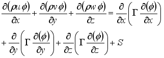
1. Introduction
Flotation machines are extensively used in industry for separating valuable minerals from a mixture with gangue minerals. It uses bubbles as carriers to attach to hydrophobic particles due to strong adhesion force and lift them into a froth layer, whilst hydrophilic particles settle to the bottom of the flotation device and come out in the tailings. This selective process is achieved based on the difference in hydrophobicity of particles, where valuable mineral particles are generally hydrophobic in nature or may be rendered hydrophobic property by the addition of collector compounds. which are utilized in petrochemical refining, water treatment, mineral processing, and deinking of recycled paper, and many other applications . The interaction between bubbles and particles plays a crucial role in determining the efficiency of the flotation process . The collision process between particles and bubbles primarily relies on the fluid dynamics factors within the flotation tank, as well as the size and quantity of particles and bubbles . The regions with high local energy dissipation are key areas for achieving bubble dispersion and particle separation during micro-processing , the particle-bubble attachment predominantly occurs in regions with high energy dissipation rates . The effectiveness of flotation machines largely depends on the initial contact between bubbles and mineral particles and the distribution of bubbles significantly affects particle flotation .
Currently, research on the complex dynamic process within a flotation machine is mainly conducted through numerical simulation and experimental methods. Early research simplified the particle as point masses, neglecting their impact on bubbles and the surrounding fluid . Bubbles were also considered rigid spheres, assuming no deformation occurred during collision and attachment processes . However, as research advanced, our understanding of the particle-bubble interaction process deepened. The gravity, and roughness of particles, as well as the size, deformation, and surface mobility of bubbles, gradually became part of the scope of study . The frother and salt within flotation can enhance bubble breakup and the solid phase within the flotation cell promotes bubble breakup and attachment , frother induced bubble breakup usually results in smaller-sized bubbles . Improving gas-liquid shear mixing can effectively change the aspect ratio of bubbles, thereby reducing their rise velocity, increasing the gas content of the liquid, and enhancing the bubble surface area flux . Given the complex interactions occurring in the flotation process, many researchers have investigated the effect of turbulence on the flotation process , the influence of turbulence generation inside the flotation machine on bubbles and particles both are significant, turbulence affects the evolution process of bubbles, ultimately impacting their distribution and the presence of bubbles also alter the local turbulence characteristics. In addition, with the developments of sophisticated experimental tools, laser Doppler velocimetry (LDV) and particle image velocimetry (PIV) have been used to gain a more detailed understanding of the hydrodynamics . LDV and hot film anemometry are capable of measuring velocity of high temporal resolution. PIV method is a widely-accepted technique in the measurements of flow fields for the reason that it could be used to measure the length scales and spatial patterns of flow structures. Used experimental method the turbulence characteristics and the effects of concentration and pressure on bubble size in the riser were studied.
Although extensive research on the hydrodynamic characteristics of flotation cells has been made, but current research efforts are mostly concentrated on the study of the hydrodynamic characteristics of bubbles and particles in flotation cells, numerical simulation of the fluid distribution in flotation cells, optimization and scaling design of bubble transport, structure, and optimization design, and there is little research on the bubble generation mechanism and the distribution, interaction process of bubbles in flotation cells, as well as the fluid dynamic characteristics of bubbles. Some numerical simulations of bubble distribution can only obtain the macroscopic air content distribution, and experimental studies are mostly carried out by extracting bubbles from a certain area and measuring the bubble size parameters. Research on the bubble breakup process in flotation cells is still relatively deficient.
Therefore, use numerical simulation method to study the fluid dynamics characteristics of bubbles and reveal the formation and movement of bubbles in the flotation machine is very important for the optimization design and large-scale design of the flotation machine. This paper aims to study the bubble breakup behavior in a KYF-0.2m3 flotation cell with ANSYS Fluent based on VOF interface tracking method and sliding mesh method. Studied the influence mechanism of operating parameters on bubble breakup by analyzing the breakup process of a single bubble at different initial positions and different impeller speed.
2. Physical Model
2.1. Computational Model
KYF-0.2m³flotation machine is an experimental flotation machine designed by Beijing Mining and Metallurgy Research Institute, which has a tank diameter of 720mm and a height of 640mm. It uses a backward inclined impeller with a diameter of 240mm and a stator diameter of 390mm. The impeller is equipped with a gas distributor at its center, the internal fluid domain of the flotation machine was divided into the impeller region, stator region, and tank region. The computational model employed for this study is illustrated in Figure 1.
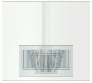
Figure 1. Computational model.
2.2. Grid Partitioning
In flotation machines, the bubble breakup mainly occurs in the agitation zone where the impeller and stator are located. In order to capture as many bubble sizes as possible while considering limitations of computer resources, the impeller region, stator region, and tank region are separately partitioned into grids. The impeller and stator regions are locally refined, and the entire computational model is divided using tetrahedral grids. The grid partitioning scheme is presented in Figure 2.
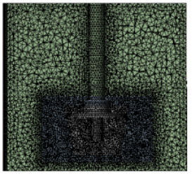
Figure 2. Image of the model’s grid partitioning.
2.3. Mathematical Model
The breakup and coalescence of bubbles in flotation machines belong to typical free surface problems, therefore, the Volume of Fluid (VOF) model is adopted in this paper for simulation purposes, each phase shares a set of equations to calculate the percentage of each fluid domain within the overall computational domain volume. The flow field inside the flotation machine involves complex turbulent flow of gas, liquid, and solid phases. In this study, the influence of solid particles is neglected, and only consider interaction between the liquid and gas phases. Both the gas and liquid phases are treated as incompressible fluids, the continuity and momentum equations for the incompressible two-phase flow can be expressed as:
xi(ρvi)=0(1)
t(ρv)+(ρvv)=-p+[μ(v+vT)]+ρg+F(2)
Where F is the surface tension of the gas-liquid interface, and µ is the dynamic viscosity coefficient of the fluid. The turbulent control equation is as follows:
(3)
Where ϕ is a generalized variable, which can represent either k or ε; Γ represents the generalized diffusion coefficient, and S represents the source term. For the k equation and ε equation, the generalized diffusion coefficient can be respectively represented as:
(4)
(5)
Where η represents the viscosity coefficient, ηt is the turbulent viscosity coefficient, and the turbulent model coefficients σk=1.0 and σε =1.3. The initial value of k can be calculated as 5% of the initial kinetic energy, while ε can be calculated using the following equation:
(6)
Cµ is the empirical coefficient in the turbulent model, which is typically set to 0.09, and l represents the length scale of turbulence.
The specific meaning of the VOF method is to define a scalar field function α to characterize the volume content of the second phase in the calculation grid. When α= 1, all gas is in the grid; when α= 0, all liquid is in the grid; when 0 <α< 1, the mixture of gas and liquid is in the grid, The governing equation is:
t(αiρi)+(αiρiv̅i)=0(7)
For two-phase flow, fluid properties are described by the following equation:
ρ=(1-α)ρl+αρg(8)
μ=(1-α)μl+αμg(9)
2.4. Boundary Conditions and Grid Independence Verification
2.4.1. Boundary Conditions
In order to show the rotation of the rotor, the impeller region is set as a rotating zone with a rotational angular velocity equal to the impeller speed. The adjacent walls of the impeller are set as moving walls with a relative velocity of 0. Other walls are treated as standard wall functions and subjected to no-slip conditions. Since this study focuses on simulating the breakup of a single bubble in the flotation machine, the influence of gas/liquid phase inlets and outlets is not considered. Therefore, all inlet and outlet surfaces are treated as walls. The initial parameters of the bubble are determined through initialization.
2.4.2. Grid Independence Verification
The accuracy of CFD calculations greatly relies on the quality of grid partitioning. In this study, To assess the influence of grid partitioning on calculation accuracy, three grid partitioning schemes were established. Each scheme utilized different grid sizes for the impeller, stator, and tank regions. The effects of grid partitioning on the calculation results were investigated for three grid sizes: 5 × 5 × 20mm, 5 × 8 × 25mm, and 5 × 8 × 20mm. The velocity distribution of the flotation machine structure at the same cross-section for three grid cell sizes is shown in Figure 3.
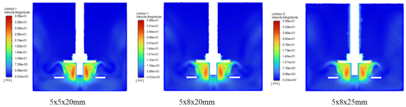
Figure 3. Velocity distribution in longitudinal section.
From Figure 3, it can be observed that when the grid size is 5 × 8 × 25mm, there is a certain deviation in both the velocity field distribution and the maximum velocity value on the cross-section of the flotation machine compared to the other two grid sizes. However, as the grid size is further reduced to 5 × 8 × 20mm and 5 × 5 × 20mm, the velocity field distribution is essentially the same. Moreover, the maximum and minimum velocity values are almost identical. This suggests that when the grid size is smaller than 5 × 8 × 20mm, more accurate calculation results can be obtained.
In VOF model, the calculation of the interface position relies on the calculation of the volume fractions of each phase. In order to improve simulation of the bubble breakup process and capturing the interaction between multiple bubbles, the grid in the agitation zone where the impeller and stator are located was refined. Considering computational resources, the grid size in the agitation zone was set to 2mm for the calculation.
3. Analysis of the Calculation Results
3.1. Flow Field Distribution
The flow field distribution has a significant impact on the breakup and distribution of bubbles within the flotation machine. In order to investigate the bubble breakup process inside the flotation machine, the velocity field within the machine was analyzed. The velocity distribution was obtained for transverse cross-sections at z=50mm from the impeller cover plate, as well as for longitudinal cross-sections, with impeller speeds of 225 r/min, 288 r/min, and 325 r/min. These results are displayed in Figure 4 and Figure 5.
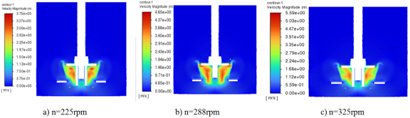
Figure 4. Velocity distribution in longitudinal section.
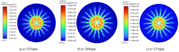
Figure 5. Cross section velocity distribution in z=50mm.
From the velocity distribution plots at the longitudinal cross-section, it can be observed that a distinct upper and lower circulation flow was exited within the flotation machine. One circulation flow region is formed above the impeller cover plate, while another flow circulation region is formed below it. The maximum velocity is located in the impeller region, and as the impeller speed increases, the flow velocity also increases, which is consistent with the flow field distribution characteristics within the flotation machine .
Furthermore, from the transverse cross- sectional velocity distribution plots, it can be seen that due to the counterclockwise rotation of the impeller, the fluid in the impeller region is thrown out under the action of centrifugal force, forming a high-velocity region near the impeller’s surface of confronting pulp. then it impacts on the stator’s surface of confronting pulp and jets out along the direction of the stator blades, resulting in higher flow velocity on the stator’s fronting surface. Additionally, due to the swirling effect, there is also a high-velocity distribution on the impeller’s back surface. Recirculation phenomena exist in the stator region and the impeller region.
3.2. The Effect of Impeller Speed on Bubble Breakup
In order to analyze the effect of impeller speed on bubble breakup behavior, this study analyzed the bubble breakup process at different speeds. The initial position of the bubble was assumed to be in the middle of the gas distributor (at a distance of z=50mm from the impeller cover plate). The initial diameter of the bubble was 5mm, and it was positioned at1mm away from the gas distributor wall. The bubble distributions at different time steps with impeller speeds of n=225r/min, n=288r/min, and n=325r/min are shown in Figure 6(a), Figure 6(b), and Figure 6(c), respectively.
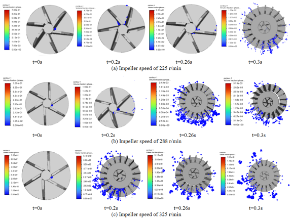
Figure 6. The distribution of bubbles at different impeller speed.
From the figures, it can be observed that bubble breakup mainly occurs at the region between the impeller and the stator, as well as in the stator region. At the initial moment the bubble is close to the axis of rotation and experience less centrifugal force. Due to the gap between the gas distributor and the impeller, the bubbles breakup under the influence of the impeller and enter different regions of the impeller blades. Subsequently, the bubbles will move along the wall of the back surface of the impeller with the rotation of the impeller under the action of centrifugal force and fluid flow, and the initial breaking will occur. The broken bubbles will move along the impeller wall. When the bubbles moves to the intersection area between the impeller and the stator, due to the action of the stator and the disturbance of the flow field, the bubbles will break away from the impeller wall and fully breakup in the stator region. Ultimately, the bubbles break into smaller ones and distributed throughout the space within the stator region by the fluid flow. With the increase of impeller speed, the centrifugal force subjected to the bubbles will also increase, and the maximum flow velocity of the fluid also increases. Bubbles can breakup quickly under the action of centrifugal force and flow field. Due to the swirling effect, Some of the breakup bubbles distribute to other regions of the impeller through the gap between the impeller and the gas distributor. Another portion of the broken bubbles moves along the impeller wall to the stator region, where they achieve a more uniform distribution under the action of the stator.
The distribution of the maximum volume fraction of gas phase with different impeller speeds is shown in Figure 7.
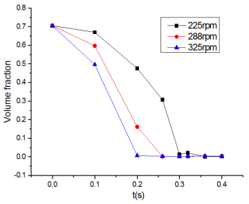
Figure 7. Maximum volume fraction of gas phase.
From Figure 7, it can be observed that bubble breakup occurs in both the impeller region and the stator region. The volume fraction of the gas phase gradually decreases over time, that means the bubble has broken. As the impeller speed increases, the bubbles can break into smaller ones more rapidly, while decreasing the impeller speed leads to a longer bubble breakup time. The variations in impeller speed ultimately impact the flow field within the flotation machine. This demonstrates the significant influence of flow field parameters on bubble breakup.
3.3. The Effect of the Radial Position of the Bubble
When the gas flow rate changes in the flotation machine, the velocity of bubbles entering flotation machine through the gas distributor also changed, This leads to different initial radial positions of the bubbles in the impeller region. In order to analyzed the influence of bubbles initial velocity on bubble breakup. This paper analyzes the breakup of bubbles with initial radial distances of 4mm and 7mm from the gas distributor wall, based on the initial bubble radial distance of 1mm from the gas distributor wall. The distributions of bubbles at different time under an impeller speed of n=225r/min with initial radial distances of x=4mm and x=7mm from the gas distributor wall are shown in Figure 8.
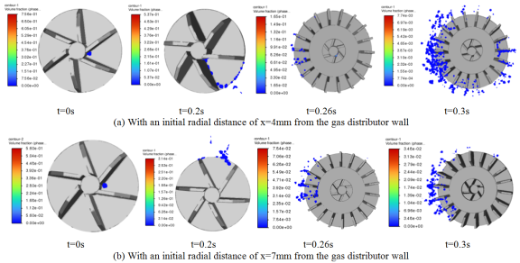
Figure 8. The distribution of bubbles at different distance.
From the Figure 8, it can be observed that as the distance from the gas distributor wall increases, the centrifugal force also increases. This results in a shorter residence time of the bubble in impeller region and a lower degree of bubbles breakup. But the bubbles can quickly move to the stator region with a short period of time. After bubble breakup, the distribution of bubbles around the stator is relatively concentrated. On the other hand, as the distance from the gas distributor wall decreases, the centrifugal force decreases. Additionally, due to the swirling effect near the impeller shaft, the bubble tends to stay in impeller region for a longer time, which lead to more bubbles breakup. These broken bubbles enter the stator region at different time steps and further contribute to the bubble breakup process. As a result, a more uniform distribution of bubbles can be obtained in the vicinity of the stator. The distribution of the maximum volume fraction of the gas phase at different time steps for different radial distances is shown in Figure 9.
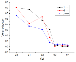
Figure 9. Maximum volume fraction of the gas phase.
Based on the previous velocity field distribution, it can be observed that there are high-velocity regions on both sides of the impeller, and a low- velocity recirculation region near the impeller shaft. When the initial position of the bubble is close to the gas distributor wall, it is influenced by the low-velocity recirculation region. During the initial process, the bubble breakup and deformation in the gap between the impeller and the gas distributor, resulting in a higher volume fraction of the gas phase. However, at a distance of 4mm from the gas distributor wall, the bubble is further away and is affected less by the low-velocity recirculation region, causing the volume fraction of the gas phase at 0.2s to be higher than that at 1mm.
When the initial position of the bubble is 7mm away from the gas distributor wall, the low-velocity reflow region has minimal impact on the bubble. As a result, the bubble can quickly move to the stator region within a short period of time and achieve a smaller volume fraction of the gas phase. This indicates that the initial position of the bubble also influence bubbles breakup. Therefore, if the initial position of the bubbles is further away from the rotating axis, the time required for bubble breakup becomes shorter.
3.4. The Effect of the Axial Position of the Bubble
Due to the gas distributor of the KYF flotation machine is a cylindrical porous structure, the gas will be in different axial positions after flowing out of the small holes. In order to analyze the influence of different axial positions on the bubble breakup process, a comparison was made regarding the breakup process of individual bubbles at distances of 25mm, 75mm from the impeller cover based on the initial conditions mentioned above. The distribution of individual bubble at 25mm position is shown in Figure 10(a) and the distribution at 75mm position is shown in Figure 10(b).
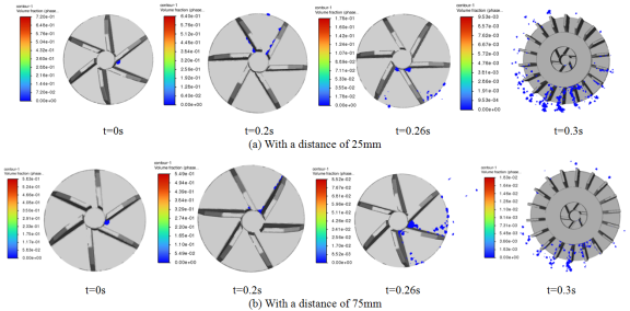
Figure 10. The bubble distribution.
From the Figure 10, it can be found that when the initial position of bubble is closer to the impeller cover, it is more influenced by the fluid near-wall. The bubble breakup mainly occurs in the impeller and stator regions. The number of broken bubbles in the impeller region is small, but after passing through the stator region, the number of broken bubbles increases and the size of the bubbles become smaller. On the other hand, when the initial position of the bubble is farther from the impeller cover, the bubble breakup process is more influenced by fluid disturbances. When the bubble reaches the rear region of the impeller blades, it will break in a short time and then spread to the stator area. Additionally, when z=25mm and z=50mm (Figure 6(a)), the distribution of bubbles within the tank is more uniform compared to z=75mm. The distribution becomes more uniform when the bubble is closer to the impeller cover due to the influence of the impeller rotation on the bubbles. As the bubble moves farther from the impeller cover, the influence of impeller on the bubbles diminish, while the influence of the flow field distribution become greater.
4. Conclusions
Through calculation, it can be found that there are two flow circulation regions in KYF flotation machine: the upper and lower regions. Under the action of the flow field and the impeller, the bubbles will break in the impeller region, but the bubbles break mainly occur in the junction area between the impeller and stator and the stator region. The broken bubbles move along the back surface of impeller due to the swirling flow. As the bubbles reach the junction area between the impeller and stator, they will detach from the impeller wall surface. In stator region, bubbles undergo further breakup due to the action of stator and the disturbance of flow field. With the increase of impeller speed, the centrifugal force becomes greater and the fluid velocity increases. This results in a shorter duration of bubble breakup and an enhanced bubble breakup effect. At the same time, with the initial distance of bubbles from the impeller axis decrease, the influence of reflow become larger. Although the time of bubble breakup is prolonged, but the bubble breakup effect is enhanced. Conversely, when the initial distance of bubbles from the impeller axis increase, the influence of main- stream fluid on the bubble becomes larger. In a short period of time, bubbles broken and enter the stator region, but the bubble breakup effect declines. when the distance between the bubble and the impeller cover decreases, the influence of the impeller on bubble increases, resulting in a more uniform distribution of bubbles and enhanced the bubble breakup effect. On the contrary, when the distance between the bubble and the impeller cover increases, the influence of fluid flow on bubble increase, while the influence of the impeller on bubble decreases. Consequently, the distribution of bubbles become less uniform and the bubble breakup effect decline. From these observations, it can be seen that the initial parameters of the bubble and the impeller speed have a significant impact on bubble breakup. Increasing the gas velocity and improving the impeller speed are beneficial to bubble breakup.
Abbreviations

CFD

Computational Fluid Dynamics

LDV

Laser Doppler Velocimetry

PIV

Particle Image Velocimetry

VOF

Volume of Fluid

Funding
(1) State Key Laboratory Open Fund for Mineral Processing Science and Technology (BGRIMM-KJSKL-2023-13).
(2) Open Research Fund of Hubei Provincial Key Laboratory for Disaster Prevention and Mitigation (Three Gorges University) (2022KJZ18).
Data Availability Statement
The datasets used and/or analyzed during the current study available from the corresponding author on reasonable request.
Conflicts of Interest
The authors declare no conflict of interest.
References
[1] A. R. Sarhan, J. Naser, G. Brooks. CFD model simulation of bubble surface area flux in flotation column reactor in presence of minerals. International Journal of Mining Science and Technology 28, 999–1007 (2018).
[2] Ahmadi R, Khodadadi DA, Abdollahy M, Fan M. Nano-microbubble flotation of fine and ultrafine chalcopyrite particles. Int J Min Sci Technol 24(4), 559–66 (2014).
[3] Guichao Wanga, Linhan Geb, Subhasish Mitra, et al. A review of CFD modelling studies on the flotation process. Minerals Engineering 127, 153–177 (2018).
[4] Xing, Y., Gui, X., Pan, L., Pinchasik, B.- E., Cao, Y., Liu, J., Kappl, M., Butt, H.-J.: Recent experimental advances for understanding bubble-particle attachment in flotation. Advances in colloid and interface science 246, 105–132 (2017).
[5] Yoon, R.-H., Soni, G., Huang, K., Park, S., Pan, L.: Development of a turbulent flotation model from first principles and its validation. International Journal of Mineral Processing 156, 43–51 (2016).
[6] Brabcov´a, Z, Karapantsios, T, Kostoglou, M, Basaˇrov´a, P, Matis, K.: Bubble–particle collision interaction in flotation systems. Colloidsand Surfaces A: Physicochemical and Engineering Aspects 473, 95–103 (2015).
[7] Huang, Z., Legendre, D., Guiraud, P.: Effect of interface contamination on particle–bubble collision. Chemical engineering science 68(1), 1–18 (2012).
[8] Schubert, H., Bischofberger, C.: On the micro- processes air dispersion and particle-bubble attachment in flotation machines as well as consequences for the scale-up of macroprocesses. International journal of mineral processing 52(4), 245–259 (1998).
[9] Schubert, H.: On the turbulence-controlled microprocesses in flotation machines. International journal of mineral processing 56(1-4), 257–276 (1999).
[10] Krasowska, M., Malysa, K., Beattie, D. A.: Recent advances in studies of bubble-solid interactions and wetting film stability. Current Opinion in Colloid & Interface Science 44, 48–58 (2019).
[11] Le Zhao, Dadong Liu, Jichao Lin, et al. Estimation of turbulent dissipation rates and its implications for the particle-bubble interactions in flotation. Minerals Engineering 201, 1–9 (2023).
[12] Koh, P., Schwarz, M.: Modelling attachment rates of multi-sized bubbles with particles in a flotation cell. Minerals Engineering 21(12-14), 989–993 (2008).
[13] Flint, L., Howarth, W.: The collision efficiency of small particles with spherical air bubbles. Chemical Engineering Science 26(8), 1155–1168 (1971).
[14] Krasowska, M., Zawala, J., Malysa, K.: Air at hydrophobic surfaces and kinetics of three phase contact formation. Advances in colloid and interface science 147, 155-169 (2009).
[15] Nagaraj, D., Farinato, R.: Evolution of flotation chemistry and chemicals: A century of innovations and the lingering challenges. Minerals Engineering 96, 2–14 (2016).
[16] Kracht, W., Finch, J.: Bubble break-up and the role of frother and salt. International Journal of Mineral Processing 92(3-4), 153–161 (2009).
[17] Yan Y, Yang W, Fang, X, Yan, P, Tu, J.: Experimental investigation of multi-phase hydrodynamics and bubble-particle interactions in a wemco 56 flotation cell. Minerals Engineering 172, 107115 (2021).
[18] Wang, C., Wang, C., Yu, A., Zheng, M., Khan, M. S.: Effect of closure characteristics of annular jet mixed zone on inspiratory performance and bubble system. Processes 9(8) (2021).
[19] Zhu, H., Valdivieso, A. L., Zhu, J., Song, S., Min, F., Arroyo, M. A. C.: A study of bubble size evolution in jameson flotation cell. Chemical Engineering Research and Design 137, 461–466 (2018).
[20] Zhang, W., Nesset, J. E., Finch, J. A.: Bubble size as a function of some situational variables in mechanical flotation machines. Journal of Central South University 21(2), 720–727 (2014).
[21] Chu, P., Waters, K. E., Finch, J. A.: Break-up in formation of small bubbles: Break-up in a confined volume. Colloids and Surfaces A: Physicochemical and Engineering Aspects 503, 88–93 (2016).
[22] Wang, H., Yang, W., Yan, X., Wang, L., Wang, Y., Zhang, H.: Regulation of bubble size in flotation: A review. Journal of Environmental Chemical Engineering 8(5), 104070 (2020).
[23] Yao, N., Liu, J., Sun, X., Liu, Y., Chen, S., Wang, G.: A rational interpretation of the role of turbulence in particle-bubble interactions. Minerals 11(9), 1006 (2021).
[24] Li, D., Wang, H., Yang, L., Yan, X., Wang, L., Zhang, H.: Intensification effects of stirred fluid on liquid–solid, gas–liquid and gas–solid interactions in flotation: A review. Chemical Engineering and Processing-Process Intensification 152, 107943 (2020).
[25] Darabi, H., Koleini, S. J., Deglon, D., Rezai, B., Abdollahy, M.: Particle image velocime- try study of the turbulence characteristics in an aerated flotation cell. Industrial & Engineering Chemistry Research 56(46), 13919–13928 (2017).
[26] Newell R, Grano S. Hydrodynamics and scale up in Rushton turbine flotation cells: Part 1 — Cell hydrodynamics. International Journal of Mineral Processing, 81(4): 224-236 (2007).
[27] Brito-Parada, P. R., Cilliers, J. J., Experimental and numerical studies of launder configurations in a two-phase flotation system. Miner. Eng. 36–38, 119–125 (2012).
[28] Erico Tabosa, Kym Runge, Peter Holtham. The effect of cell hydrodynamics on flotation performance. International Journal of Mineral Processing. 156: 99–107 (2016).
[29] Shen Zhengchang, Lu Shijie, Shi Shuaixing etal. Single-phase flow field measurement and analysisbased on PIV for KYF flotation machine-Flow field measurement and simulation research on KYF flotation machine (I). Nonferrous Metals (Mineral Processing Section), 1: 59-64 (2013).
Cite This Article
  • APA Style

    Zhou, J., Lin, J., Yuan, X., Mao, Z. (2024). Research of Bubble Breakup and Influencing Factors in Flotation Machine. International Journal of Mineral Processing and Extractive Metallurgy, 9(1), 1-10. https://doi.org/10.11648/j.ijmpem.20240901.11

    Copy | Download

    ACS Style

    Zhou, J.; Lin, J.; Yuan, X.; Mao, Z. Research of Bubble Breakup and Influencing Factors in Flotation Machine. Int. J. Miner. Process. Extr. Metall. 2024, 9(1), 1-10. doi: 10.11648/j.ijmpem.20240901.11

    Copy | Download

    AMA Style

    Zhou J, Lin J, Yuan X, Mao Z. Research of Bubble Breakup and Influencing Factors in Flotation Machine. Int J Miner Process Extr Metall. 2024;9(1):1-10. doi: 10.11648/j.ijmpem.20240901.11

    Copy | Download

  • @article{10.11648/j.ijmpem.20240901.11,
      author = {Jianjun Zhou and Jingjun Lin and Xianbao Yuan and Zhangliang Mao},
      title = {Research of Bubble Breakup and Influencing Factors in Flotation Machine
    },
      journal = {International Journal of Mineral Processing and Extractive Metallurgy},
      volume = {9},
      number = {1},
      pages = {1-10},
      doi = {10.11648/j.ijmpem.20240901.11},
      url = {https://doi.org/10.11648/j.ijmpem.20240901.11},
      eprint = {https://article.sciencepublishinggroup.com/pdf/10.11648.j.ijmpem.20240901.11},
      abstract = {As the core factor of flotation, bubbles have an important effect on flotation. The rotor speed, initial gas parameters and impeller structure of the flotation machine will affect the formation and movement of bubbles. It is very important to study the influence mechanism of operating parameters of flotation machine on the bubble breakup process for flotation machine design and structure optimization. This paper takes KYF-0.2m3 flotation machine as the research object, establishes a single bubble analysis model, adopts the VOF (Volume of Fluid) method to analyze the influence of different initial positions of bubbles on the bubble breakup behavior, and studies the influence of impeller speed and initial position of bubbles on the bubble breakup. Result show that the breakup of bubbles mainly occurs near the stator region. With the increase of rotational speed of the impeller, the centrifugal force and the disturbance of the convection field will become greater, the time of the bubble breakup become shorter, more bubbles breakup and generate more smaller ones. With the bubble position is closer to the rotating axis of the impeller, the impact of reflow becomes stronger and the bubble breakup effect will be better, and if the bubble initial position closer to the impeller cover, the influence of impeller on the bubbles become greater and the distribution of bubbles will be more uniform.
    },
     year = {2024}
    }
    

    Copy | Download

  • TY  - JOUR
    T1  - Research of Bubble Breakup and Influencing Factors in Flotation Machine
    
    AU  - Jianjun Zhou
    AU  - Jingjun Lin
    AU  - Xianbao Yuan
    AU  - Zhangliang Mao
    Y1  - 2024/08/27
    PY  - 2024
    N1  - https://doi.org/10.11648/j.ijmpem.20240901.11
    DO  - 10.11648/j.ijmpem.20240901.11
    T2  - International Journal of Mineral Processing and Extractive Metallurgy
    JF  - International Journal of Mineral Processing and Extractive Metallurgy
    JO  - International Journal of Mineral Processing and Extractive Metallurgy
    SP  - 1
    EP  - 10
    PB  - Science Publishing Group
    SN  - 2575-1859
    UR  - https://doi.org/10.11648/j.ijmpem.20240901.11
    AB  - As the core factor of flotation, bubbles have an important effect on flotation. The rotor speed, initial gas parameters and impeller structure of the flotation machine will affect the formation and movement of bubbles. It is very important to study the influence mechanism of operating parameters of flotation machine on the bubble breakup process for flotation machine design and structure optimization. This paper takes KYF-0.2m3 flotation machine as the research object, establishes a single bubble analysis model, adopts the VOF (Volume of Fluid) method to analyze the influence of different initial positions of bubbles on the bubble breakup behavior, and studies the influence of impeller speed and initial position of bubbles on the bubble breakup. Result show that the breakup of bubbles mainly occurs near the stator region. With the increase of rotational speed of the impeller, the centrifugal force and the disturbance of the convection field will become greater, the time of the bubble breakup become shorter, more bubbles breakup and generate more smaller ones. With the bubble position is closer to the rotating axis of the impeller, the impact of reflow becomes stronger and the bubble breakup effect will be better, and if the bubble initial position closer to the impeller cover, the influence of impeller on the bubbles become greater and the distribution of bubbles will be more uniform.
    
    VL  - 9
    IS  - 1
    ER  - 

    Copy | Download

Author Information
  • Abstract
  • Keywords
  • Document Sections

    1. 1. Introduction
    2. 2. Physical Model
    3. 3. Analysis of the Calculation Results
    4. 4. Conclusions
    Show Full Outline
  • Abbreviations
  • Funding
  • Data Availability Statement
  • Conflicts of Interest
  • References
  • Cite This Article
  • Author Information